Over the last year, I started playing around with LoRaWAN, a long-range low-power wireless data transfer protocol. We internally crowdfunded a LoRaWAN gateway at Coredump and joined the Things Network. More about our gateway in a future blogpost. For a general introduction into LoRaWAN, I recommend watching this video. And this 33c3 talk is a fantastic introduction to the LoRa PHY layer.
This blogpost is not about LoRa or LoRaWAN itself though, but about a related topic: Antennas! In Europe, LoRaWAN is operated at a frequency of 868 MHz. After testing multiple antennas for LoRaWAN nodes and gateways, I wondered how these antennas can be compared. We’ll take a look at three metrics to compare antennas: Directivity, Gain and VSWR. And then – in a follow-up blogpost – I’ll present the results from a lab test of 11 different 868 MHz antennas.
First off, I want to start with saying that I’m no expert at all on antennas and RF in general. I’m a software engineer, not an electrical engineer and therefore lack some of the theoretical background needed in this field. But I learned some things in the last few months that I’d like to share. If I get something wrong, please let me know in a comment!
A document that summarizes these things better and in more detail than I will do it, is the Application Note AN-00501 by Linx Technologies. I can warmly recommend reading it for a fantastic introduction to the topic. Also, if you aren’t familiar with measuring things in decibels, I recommend reading the Networker’s Guide to Decibels.
Directivity and Gain
An antenna has a single goal: To radiate energy into space. It converts electric currents into electromagnetic waves and vice versa.
Many antenna metrics are done in reference to a so-called “ideal isotropic antenna”. That is a theoretical antenna which radiates 100% of its energy uniformly in every direction. Such an antenna does not exist physically, but we can take it as a reference.
By focussing the electromagnetic energy beam into a certain direction, the range in that direction can be extended compared to the isotropic reference antenna. The amplification in that direction compared to the isotropic antenna is called the “gain” and it’s expressed in dBi (the “i” stands for “isotropic”). Note that the total energy is always the same, so focussing the energy in one direction means losing range in another direction. You can think of it like focussing a flashlight – the center of the beam becomes brighter but the radius of the illuminated area decreases. Or think of it like a balloon – you can make it longer by squishing it together between your hands, but then it also gets thinner.
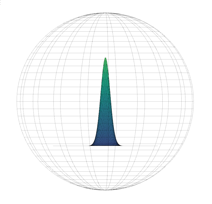
Most typical antennas used for LoRaWAN are omnidirectional, meaning that they have more or less the same range in every horizontal direction. The radiation pattern is donut-shaped in that case.
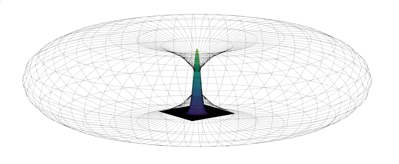
Note that we’re loosing range in the vertical direction, but gain range in the horizontal direction (if the antenna is oriented vertically in the middle of that donut shape). An antenna gain of 3 dBi would mean that we would get about twice the transmit power in horizontal direction compared to the isotropic antenna.
Resonance, VSWR
Last but not least, antennas are optimized for a certain frequency or frequency range. In our case we want the antenna to work best at 868 MHz. But how is an antenna optimized for a certain frequency?
The relation between the frequency and the wavelength can be expressed as follows:
![]()
where
f = frequency in hertz (Hz)
λ = wavelength in meters (m)
c = speed of light (299’792’458 m/s)
Calculating the wavelength of waves at 868 MHz is simple:
![]()
That means that the wavelength (λ) of a wave at 868 MHz is about 34 cm. Thanks to the laws of phyics, we don’t need to make our antenna 34cm though. It also works if we use certain fractions of that length, namely 1/2 λ or 1/4 λ.
A factor that antennas need to compensate for is the fact that the speed of electromagnetic waves in air is a bit lower than the value used above, which applies to electromagnetic waves in vacuum. Furthermore, the shape of the antenna and the presence of objects nearby also influence the resonance frequency. This means that matching an antenna perfectly to a certain frequency is tricky.
A metric to measure how well an antenna is matched to its frequency is the VSWR (Voltage Standing Wave Ratio). Since the Application Note that I linked further above can explain it much better than I could, I’ll simply quote them:
“The Voltage Standing Wave Ratio (VSWR) is a measurement of how well an antenna is matched to a source impedance, typically 50-ohms. It is calculated by measuring the voltage wave that is headed toward the load versus the voltage wave that is reflected back from the load. A perfect match will have a VSWR of 1:1. The higher the first number, the worse the match and the more inefficient the system. Since a perfect match cannot ever be obtained, some benchmark for performance needs to be set. In the case of antenna VSWR, this is usually 2:1. At this point, 88.9% of the energy sent to the antenna by the transmitter is radiated into free space and 11.1% is either reflected back into the source or lost as heat on the structure of the antenna. In the other direction, 88.9% of the energy recovered by the antenna is transferred into the receiver. As a side note, since the “:1” is always implied, many data sheets will remove it and just display the first number.”
Now that we have established the basis for comparing LoRaWAN antennas, we can go on and start measuring them. More about that – and the results of our test – in the next blogpost!