In our previous blogpost, we talked about ways to measure and compare antennas. If you haven’t read it yet, you should probably do so, unless you already know what antenna gain and VSWR are. Also, I want to reference the great Application Note AN-00501 again, which contains a lot of resources that help interpreting the following results.
Today, we’ll take a look at the results we got from antenna measurements. Since I already had a few LoRa antennas from various sources, I wanted to know how they compare. The best way to do that is with an antenna test chamber. Luckily, the people at the Institute for Communication Systems (ICOM) at HSR built themselves such a test chamber from an old SBB freight container.
Even more luckily, we were allowed to use the test chamber to do the measurements required to compare various LoRa antennas (thanks Selina!).
The Antennas
These are the antennas that we measured:
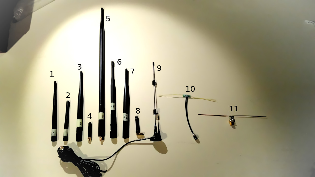
Description of the various antennas:
- Taoglas TI.08.A.0111
- Generic antenna from Urs
- Generic antenna from Urs
- Antenna from Ali Express
- High gain antenna from Alibaba
- Antenna from IMST
- Antenna from Ali Express
- ANT-868-CW-RCS-SMA from Linx Technologies
- Antenna from Ali Express with 3m RG-174 cable
- DIY dipole antenna without balun
- DIY dipole antenna with balun
How We Measured
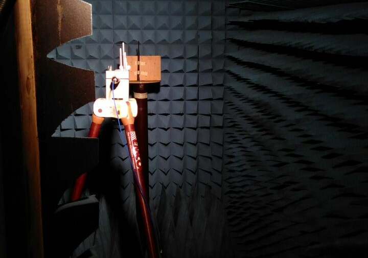
The gain measurement was conducted in the test chamber. The transmitting antenna was directed straigth at the test antenna. The test antenna was positioned vertically (unless noted otherwise) on a counterpoise / groundplane of about 20x20cm.
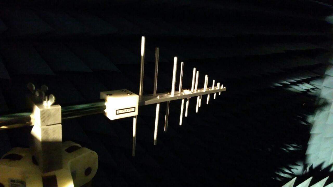
The test antenna could be rotated along the Z-axis. Every few degrees, a measurement was conducted at 868 MHz, which allows us to draw nice plots of the results.
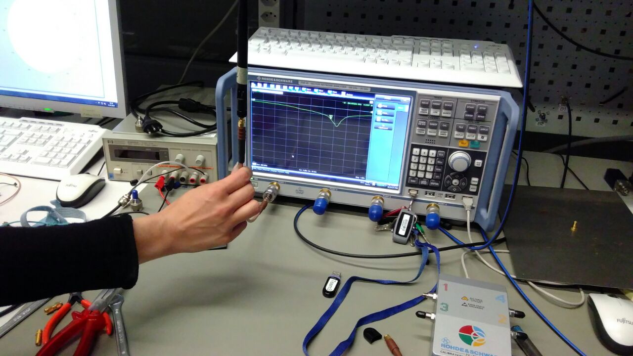
To measure the VSWR we used calibrated testing equipment from Rohde & Schwarz. Measurements were done while holding the antenna cable in our hands. Most measurements were done without a counterpoise / groundplane, unless noted otherwise. Antennas that can be bent were measured straight, unless noted otherwise.
Results: Antenna Gain
Here are the gain measurement results for the various antennas.
Notes:
- For antenna 7 we had two samples of the same product, so we measured both (7A and 7B).
- The DIY dipole antenna without balun (10) was measured twice, once in vertical orientation and once in horizontal orientation.
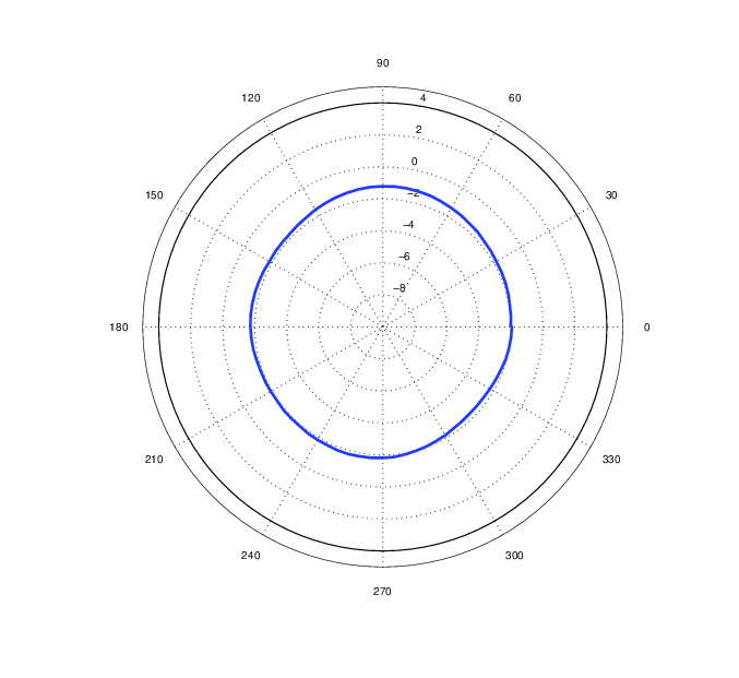
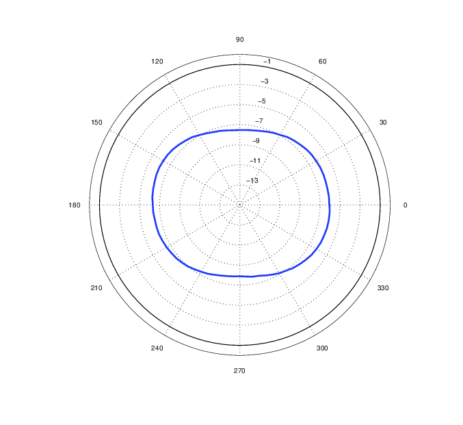

As we can see, the results were varying quite a lot. Of the first 5 antennas, only one (4) had a barely positive dBi gain. The impressive-looking long antenna (5) which was sold as a high-gain 9 dBi gain antenna by the Chinese seller even averaged at around -7 dBi.
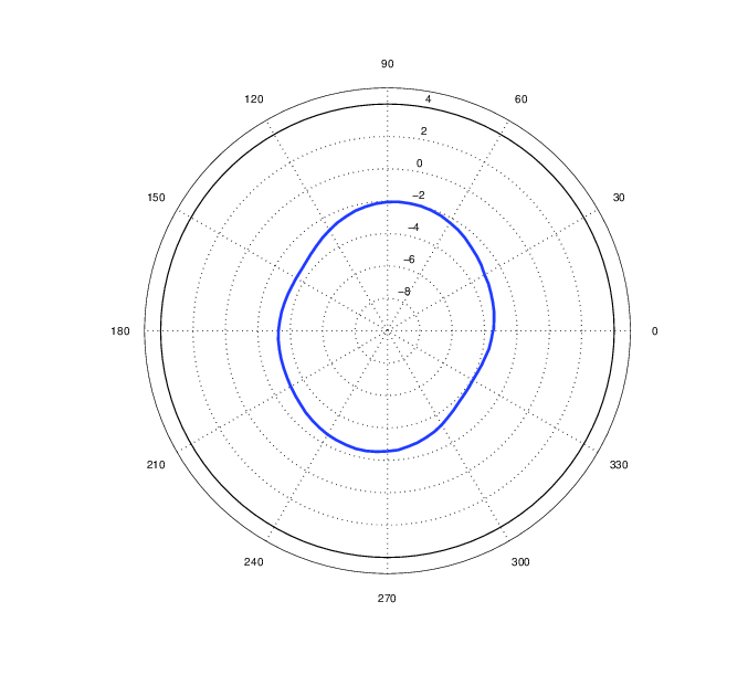
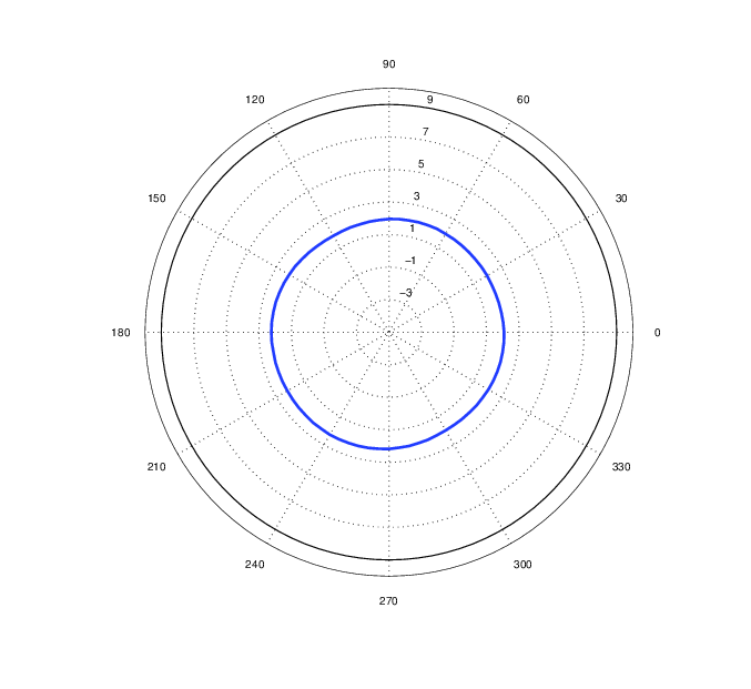
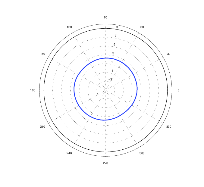
The next two results (6-7) were better. We measured the IMST antenna (6) gain at around 2 dBi, which matches their specification. For the Ali Express antenna, we measured two samples (7A and 7B), both of which were a bit above 2 dBi. This does not match their specification of 5 dBi, but hey – the antenna just costs 4$ and the gain is still slightly above the one by IMST (which is also still cheap at 7.70€).
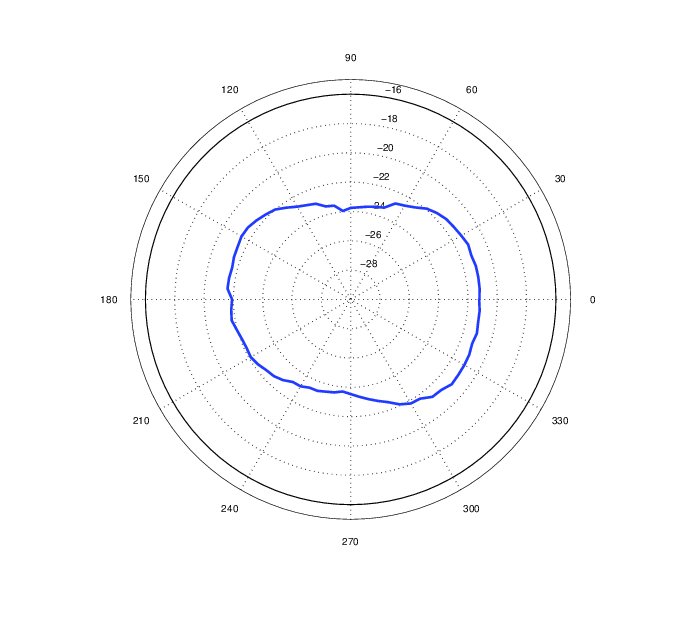
The tiny antenna by Linx Technologies (8) is specified at 3.6 dBi, but for some reason we only measured around -2 dBi. That might be due to the tricky measurement setup though. Since the antenna connector is fixed at 90° angle, we could not simply position it vertically but had to use some 90° adapters to get it positioned. That also explains the slightly squished radiation pattern, since the center of rotation was a bit off from the center of the antenna. The loss caused by those adapters, combined with tricky setup and possibly non-optimal groundplane setup probably contributed to the result.
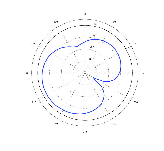
Next up, we have a 4.50$ antenna from Ali Express (9) with helical “squiggles” in the antenna design. This is done to make the antenna a bit shorter and easier to handle. The antenna specifies a whopping 7 dBi of gain. According to this calculator, the 3m of RG-174 cable should account for about 3 dBi attenuation. While that should leave us with around 4 dBi of gain, we measured between -24 dBi and -21 dBi. I’m not sure why the results are that bad, we also tried to unwrap the cable to see if it makes a difference, but it didn’t. Maybe the sample we got was faulty, or maybe it’s just crappy 🙂
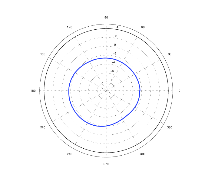
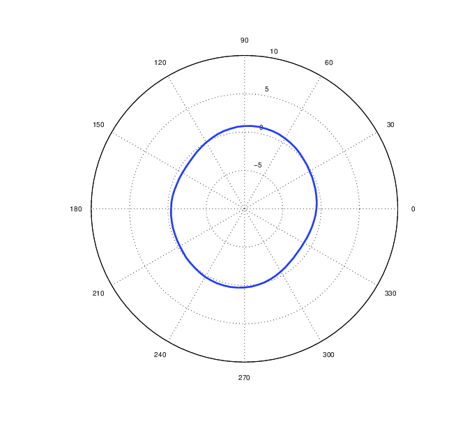
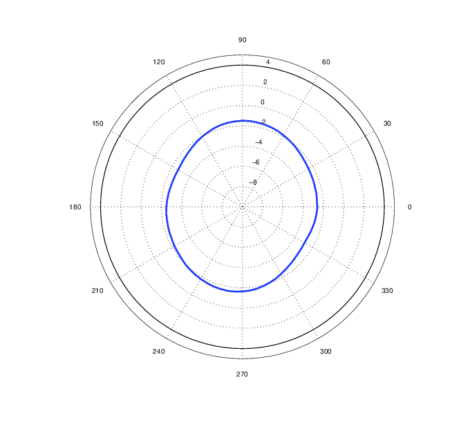
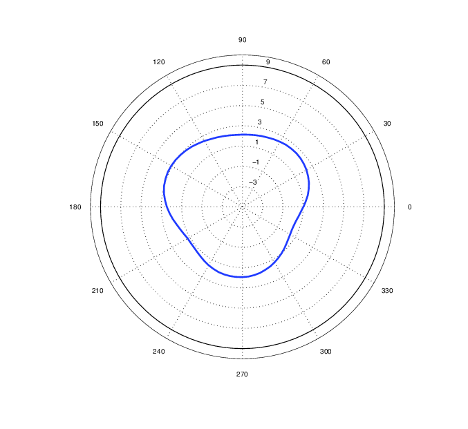
Finally, there are two DIY dipole antennas. The first one (10) was built by me based on some instructions I found online. The second one (11) was made by one of the ICOM employees after he explained to me that a dipole should have a balun to improve the radiation characteristics. As the measurements show, the radiation pattern of my dipole (10) is not nicely rounded, which can probably be attributed to the aforementioned missing balun. We also did a horizontal measurement, which should in theory look like this, but looks more like an embryo 🙂 Nevertheless, the antenna has around 1-3 dBi gain, which is nice for 10 minutes of crimping and soldering work by someone that has never built an antenna before 🙂
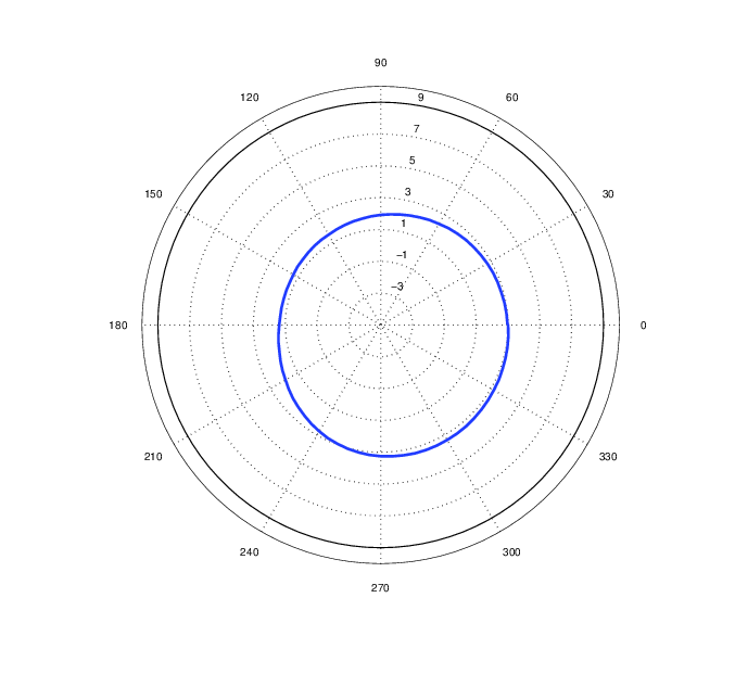
The second DIY dipole (11) has a radiation pattern that isn’t perfectly centered (maybe the positioning of the antenna was not perfect), but it’s quite nice and round, with a gain of 1-3 dBi.
Results: VSWR
Here are the VSWR measurements.
Notes:
- For antenna 7 we had two samples of the same product, so we measured both (7A and 7B).
- If not noted otherwise, measurements were done without a groundplane. For some of the antennas we did both measurements though, one without a groundplane, and one with a 20x20cm groundplane.
- Unfortunately it seems we forgot to save the VSWR measurement for antenna 9. Too bad, would have been interesting.
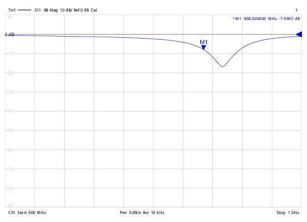
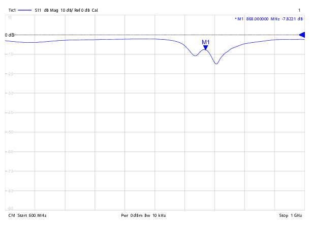
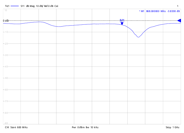
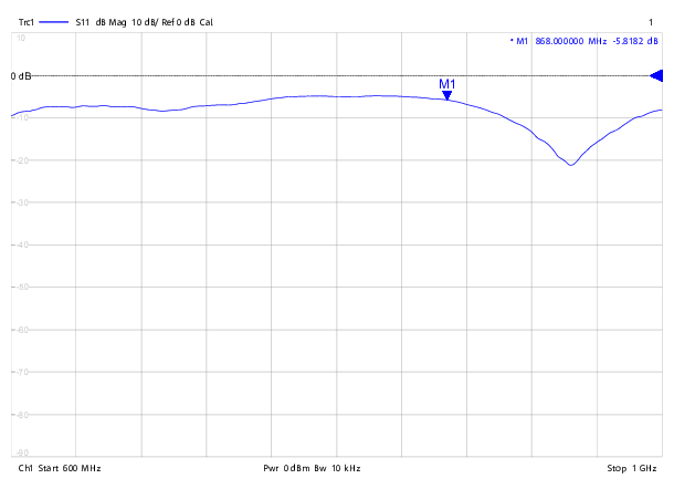
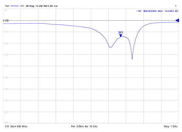
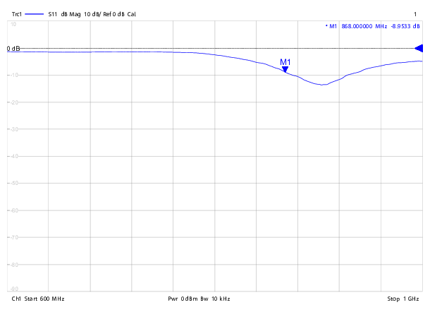
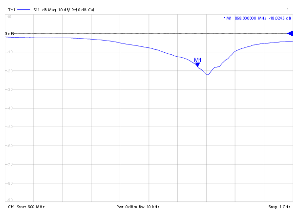
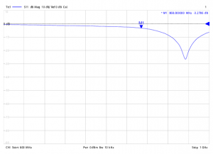
- The equipment was set to measure the range from 600 MHz to 1 GHz. A division is a step of 40 MHz.
- The measurement point M1 was set to 868 MHz.
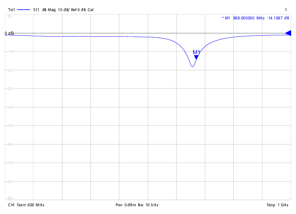
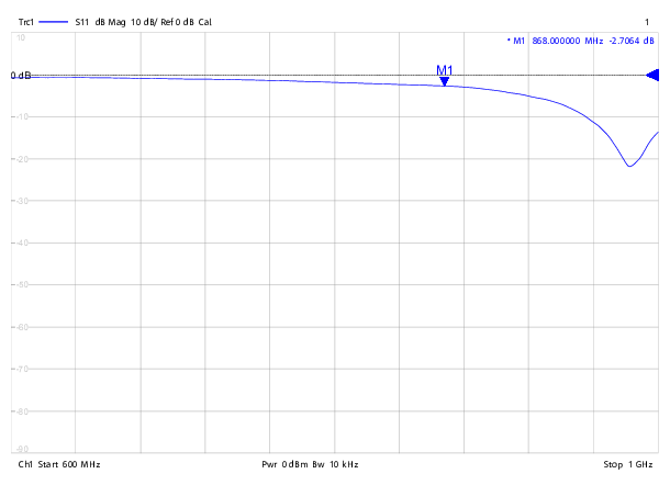
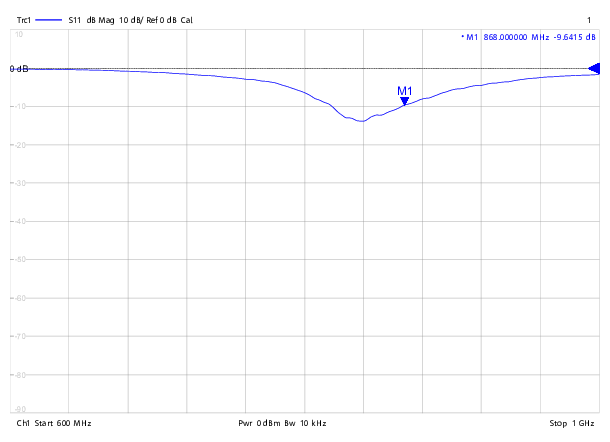
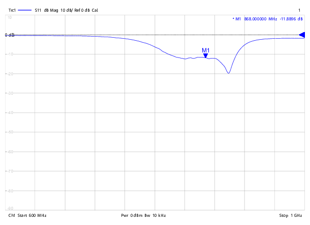
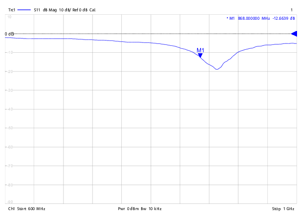
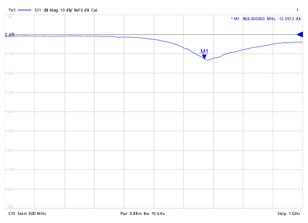
First, we need to be able to interpret these results. What we can read from these charts is the return loss in dB. For example, in the first chart, we can see that the point M1 is at -14.2 dB. To calculate the VSWR from that, we use the following formula (which I found here):
![]()
If we put in the return loss (RL) of 14.2 dB into the formula above, we end up with a VSWR of 1:1.48. Here’s the table with the calculated VSWR values:
| Antenna | Groundplane | VSWR |
|---|---|---|
| 1 | No | 1.48 |
| 2 | No | 2.32 |
| 3 (straight) | No | 2.37 |
| 3 (angled) | No | 4.60 |
| 4 | No | 6.47 |
| 4 | Yes | 1.98 |
| 5 | No | 3.10 |
| 6 | No | 1.47 |
| 6 | Yes | 1.68 |
| 7A | No | 1.61 |
| 7A | Yes | 2.11 |
| 7B | No | 1.29 |
| 7B | Yes | 1.61 |
| 8 | No | 5.36 |
| 8 | Yes | 4.33 |
| 10 | No | 1.09 |
Some comments about those results:
First of all, measuring the reflected voltage is tricky. Depending on how you hold the cable, and on whether your hand is close to the antenna or not, the result changes. Also, some types of antennas require a groundplane to work properly, e.g. quarter wave monopoles. So take all of those measurements with a grain of salt.
First, we notice that antennas that can be bent are probably optimized for straight or angled position. Antenna 3 had a VSWR of 2.37 when straight and 4.60 when angled.
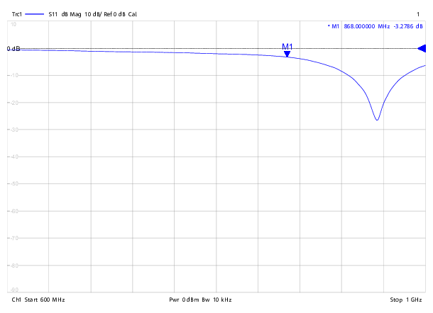
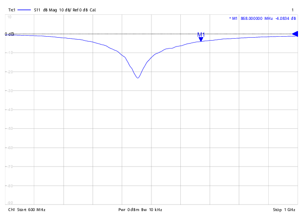
A groundplane lowers the resonance frequency of an antenna and widens the bandwith. One of the examples where we can see this best, is antenna 8, which is a quarter wave monopole:
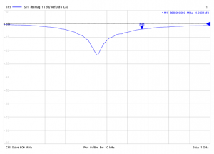
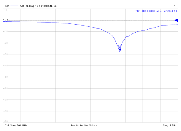
We can see that our 20×20 cm groundplane moves the resonance frequency from around 960 MHz to around 760 MHz. Because our desired frequency of 868 MHz was off in both configurations, we only got VSWR values of 5.36 and 4.33. By using a smaller groundplane, we might have hit the ideal resonance, which according to the datasheet should have resulted in a VSWR of <2.0. And they’re right, the return loss at resonance seems to be around 23 dB, which would give us a VSW ratio of 1:1.15.
Finally, a comment about antenna 10: Since this was a DIY antenna, we could optimize it perfectly for our desired frequency by cutting the wires to the perfect length. With the configuration we used, we hit the sweet spot. But that might change again once it’s attached to an enclosure 😉
All this shows the importance of choosing an antenna that matches the project. If you want a small quarter wave antenna, you need to make sure to get one that works well together with your PCB and/or enclosure. This is probably the area where theory ends and where practical approaches work better – simply try what works best. And in the end, in many cases you don’t actually need a perfect antenna, if the network coverage is good enough 🙂
Conclusion
I had fun and learned a lot by measuring those antennas. I hope you could learn something too from the report. The results also showed that it doesn’t always have to be the most expensive antenna to get good results. My favorite antenna turned out to be number 7, with a gain of 2 dBi and a VSWR of around 1.3-1.6 at 868 MHz. You can get it at Ali Express for about 4$ plus shipping.
Thanks again also to Urs, who brought me some additional antennas to test, and to Selina, who spent a few hours of her free time to conduct those measurements with us 🙂
here some information about the antennas
antennas
1 Taoglas TI.08.A.0111 (Mouser)
2 unknown piece
3 AliExpress 868M/900M/915Mhz antenna module aerial 5dbi Omni SMA male connector folding 195mm long
4 AliExpress 868M/900M/915MHz antenna 2dbi SMA male connector 5cm long
5 Alibaba High gain 868mhz whip antenna used for my Gateway (get from Gonzalo) https://www.alibaba.com/product-detail/-Manufactory-High-gain-868mhz-whip_1155413041.html?spm=a2700.8443308.0.0.saHOCP
Number 3 “should” be identical with Nr. 7
Thanks! I’ll update the post.
Regarding your number 3, it looks almost identical to my number 7, but not quite. The upper part is a bit different. So they seem to be different models.
Thank you for the informative and interesting measurements.
Do you have planed to measure also PCB antennas (traces) or SMD antennas (surface mounted device) ?
I would good to know if PCB antennas can replace external antennas for small nodes.
Somewhere I read that in this ISM Band (868 MHz) in Switzerland maximum 25mW of tx power allowed are.
Therefore you have to reduce the tx power by 2dB if you use the high-gain antennas?
A second test is not currently planned. PCB antennas should work though, depending on the use case. I’m not an antenna expert at all 🙂 Maybe just try it?
Regarding antenna gain, no, you don’t need to reduce TX power. Take a look at the first part, especially the stuff about directivity / gain. Gain does not increase the emitted power, it only changes the radiation pattern.
Thank you for your response.
It seem logical that no more energy can be transmitted than the amplifier pushes out.
So your statement is, that the emitted power is not only limited for isotropic transmission.
You could be supported by this:
Maximum Effective Isotropic Radiated Power (EIRP)
http://www.afar.net/tutorials/fcc-rules
But I am confused by this posts in thethingsnetwork forum:
https://www.thethingsnetwork.org/forum/t/compliance-need-help-to-reduce-gateway-tx-power/3287
Turns out you were right about the gain reduction (although it’s not necessary for a 2dBi antenna).
For reference, in case other people are looking at this, the discussion can be found here: https://www.thethingsnetwork.org/forum/t/compliance-need-help-to-reduce-gateway-tx-power/3287
Antenna 8 is a l/4 monopole. These type of antennas require a l/4 radius ground plane (86 mm). No wonder that with a to large ground plane the tuned frequency was to low and with a to small (missing) ground plane to high.
Other question: in the first picture one can see the horizontal ground plane and a vertical “object” to that the antenna is fixed using tape. I guess that the materials epsilon r (FR4?) influenced the radiation pattern of the test antennas Most of your antennas should have a perfect circular pattern but don’t show in our tests.